Know Your Heat Tape Type Before Testing
Heat tape is a broad term covering two fundamentally different technologies, and the testing approach for each differs in important ways. Applying the wrong test to the wrong product type leads to misread results — a functioning cable declared faulty, or a failing one cleared as operational.
Constant wattage heat tape outputs a fixed amount of heat per unit length regardless of ambient temperature. It contains two parallel conductors connected at intervals by a resistive heating element. Because its output is fixed, it can overheat if improperly installed or left running in warm conditions — and it will produce a consistent, predictable resistance reading on a multimeter when functioning correctly.
Self-regulating heat tape uses a conductive polymer core that automatically increases or decreases resistance — and therefore heat output — in response to ambient temperature. In warm conditions, the core becomes more resistive and output drops. In cold conditions, resistance falls and output rises. This means that testing a self-regulating cable with a multimeter in a warm environment will produce a high resistance reading that looks like a fault but is actually normal operation. Understanding this distinction before testing prevents incorrect diagnosis. Industrial heat trace systems and heating cables span both technologies, with self-regulating cables dominant in freeze-protection and process temperature maintenance applications due to their energy efficiency and inherent overheat protection.
To identify which type you have: check the product label or installation documentation. Self-regulating cables are typically labeled "SR," "self-regulating," or "self-limiting." Constant wattage cables may be labeled "CW," "constant wattage," or simply list a fixed wattage-per-foot specification without any temperature-response language.
Step 1 — Visual Inspection
Visual inspection is always the first step, regardless of cable type. It requires no tools, takes only a few minutes, and will immediately identify any heat tape that should be removed from service before electrical testing begins.
With the power supply disconnected, run your hand slowly along the full length of the exposed cable — do not skip sections hidden under insulation wrapping. You are looking for four specific conditions:
Insulation damage: Cracks, nicks, splits, or any point where the outer jacket has been compromised. Even minor surface damage creates a moisture ingress path that degrades the cable from the inside. Any exposed conductor wire is an immediate replacement indicator — do not reconnect power to a cable with exposed wiring.
Discoloration or char marks: Brown or black staining on the outer jacket indicates the cable has experienced a hotspot — a localized area of excessive heat output, typically caused by overlapping installation, contact with insulating material that traps heat, or a failing connection point. A charred cable must be replaced regardless of whether it still produces heat.
Mechanical damage: Kinks, sharp bends, crush points, or areas where the cable has been stapled, clamped, or fastened too tightly. These points create concentrated stress on the internal conductors that may not yet show as an electrical fault but will fail under thermal cycling.
Connection integrity: Inspect the end seal, the junction between cable and power cord, and any splice points. These are the highest-failure-rate locations in any heat tape installation. Loose connections generate resistance heat that accelerates degradation at exactly the point where moisture is most likely to enter.
If visual inspection reveals any of the above, the cable should be replaced before proceeding further. Continuing to test a visibly damaged cable does not change the outcome — it only delays the replacement decision.
Step 2 — Power Indicator and Touch Test
Many consumer and commercial heat tape products include a small LED indicator light built into the power plug. When illuminated, this light confirms that electrical current is reaching the cable. It does not confirm that the full length of the cable is heating — a break midway along the run can exist while the indicator light remains on — but it is a useful first functional check.
If the indicator light is off while the cable is plugged into a confirmed working outlet, the cable has an open circuit — either a complete break in the conductor or a failed connection at the plug end. This requires replacement.
The touch test is the simplest functional check for constant wattage cables: with the cable powered and allowed to run for five to ten minutes, carefully touch the cable surface at several points along its length. A functioning constant wattage cable should feel uniformly warm along its entire run. Cold spots indicate a break or failed heating element at that location. Hotspots — areas significantly hotter than the surrounding cable — indicate a fault such as overlapping installation or a failing element that is concentrating heat output.
For self-regulating cables, the touch test is less reliable as a standalone check. In ambient temperatures above approximately 50°F (10°C), a self-regulating cable operating normally may produce very little perceptible warmth — this is by design. In these conditions, the multimeter resistance test described in the next section provides more reliable information.
Step 3 — Multimeter Resistance Test
A multimeter set to resistance (ohms) mode provides the most accessible electrical test for heat tape without specialized equipment. The test measures the continuity and approximate resistance of the heating circuit.
Before testing: Disconnect the cable from the power supply completely. Do not perform resistance measurements on a live circuit. Allow the cable to reach ambient temperature — testing a recently powered cable produces elevated resistance readings that do not reflect resting state.
Procedure: Access the two conductor terminals at the power end of the cable — on most heat tape products these are the two blades of the power plug, or the two lead wires before the plug assembly. Place one multimeter probe on each terminal and read the resistance value displayed.
Multimeter resistance readings and what they indicate
| Reading |
Constant Wattage Cable |
Self-Regulating Cable |
| Value close to manufacturer specification |
Cable functioning normally |
Cable functioning normally (at low ambient temp) |
| High resistance / OL (overload) |
Open circuit — conductor break or failed connection |
May be normal at warm ambient temperature |
| Zero or near-zero resistance |
Short circuit — conductors in contact; replace immediately |
Short circuit — replace immediately |
| Fluctuating / unstable reading |
Intermittent fault — damaged conductor or loose connection |
Intermittent fault — inspect connections and jacket |
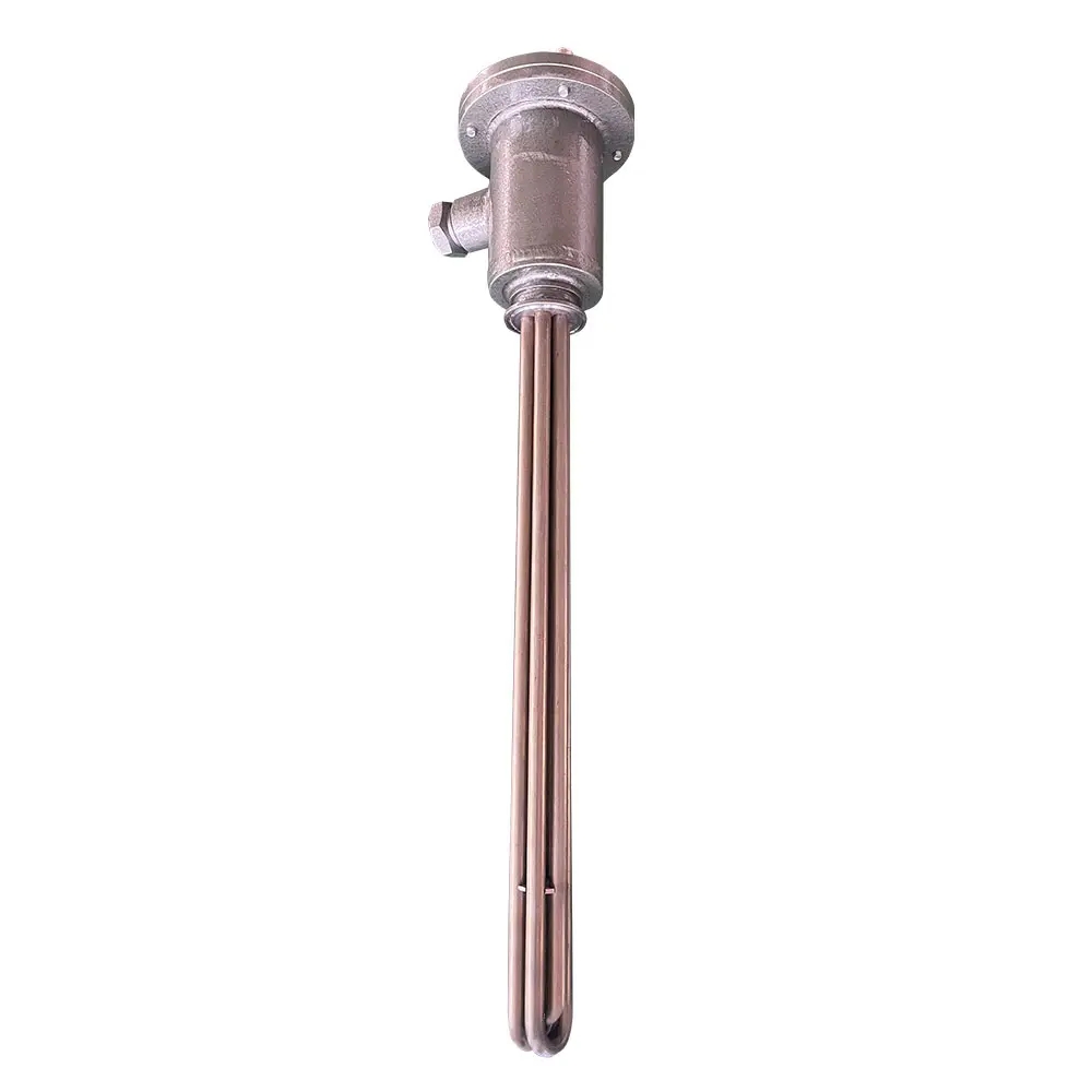
For constant wattage cables, the expected resistance value can be calculated from the product specifications: divide the rated voltage squared by the rated wattage (R = V²/W). A cable rated at 120V and 5W/ft over a 20-foot run has a total rated wattage of 100W and an expected resistance of approximately 144 ohms. A reading significantly above or below this value indicates a fault. The heating elements for industrial electric systems follow the same resistance-based diagnostic logic — knowing the rated resistance of any resistive element is the baseline against which measured values are compared.
Step 4 — Thermostat Trigger Test (Constant Wattage)
Constant wattage heat tape designed for pipe freeze protection typically includes a built-in thermostat that activates the cable when ambient temperature drops to approximately 38–40°F (3–4°C). A cable that passes visual inspection and resistance testing but fails to activate during cold weather may have a failed thermostat rather than a failed heating element — the two are separate components and fail independently.
The thermostat trigger test simulates cold conditions to verify activation without waiting for winter temperatures. The procedure requires only a sealable plastic bag and ice.
Procedure: Locate the thermostat — on most products it is a small bulge or clip mounted to the cable near the power cord end, positioned against the pipe surface. Fill a plastic bag with ice and seal it. Drape the ice bag directly over the thermostat and leave it in contact for 20 to 30 minutes. This is sufficient to drop the thermostat temperature below its activation threshold. With the cable plugged in during this period, check whether the cable begins producing heat — either via the touch test at multiple points along the run, or by monitoring the indicator light if present.
If the cable does not activate after 30 minutes of thermostat cooling, the thermostat has likely failed in the open position. Most heat tape thermostats are integral to the cable assembly and are not serviceable separately — replacement of the full cable is typically the appropriate response. If the cable activates during the ice test but was not activating in field conditions, verify that the thermostat is making good thermal contact with the pipe surface and is not suspended in free air, which delays or prevents activation.
Industrial Heat Trace: Insulation Resistance Testing
For industrial heat trace systems — process piping, tank heating, and similar applications — the standard maintenance test is insulation resistance (IR) testing using a megohmmeter (megger), not a standard multimeter. Insulation resistance testing applies a high DC voltage (typically 500V or 1000V) to the cable circuit and measures the resistance between the conductor and the earth ground braid or shield. This detects moisture ingress, insulation breakdown, and degradation that a standard multimeter resistance test cannot reveal.
The industry-accepted minimum insulation resistance for a heat trace circuit in service is 20 megohms. A reading below 20MΩ indicates insulation degradation that requires investigation before the system is returned to service. Readings in the range of 1–5MΩ indicate significant moisture ingress or insulation damage. A reading below 1MΩ is a critical failure requiring immediate isolation of the affected circuit.
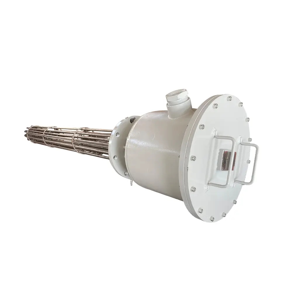
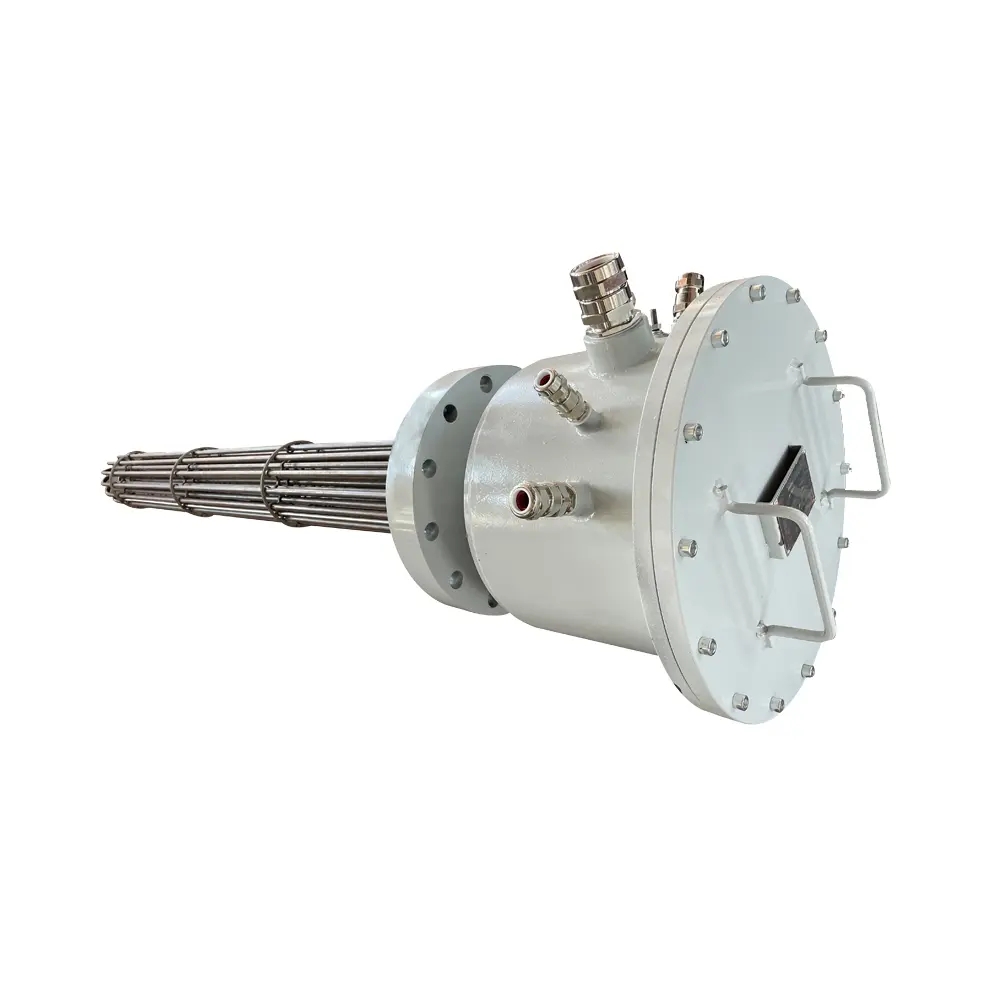
Testing procedure for industrial systems follows a structured walk-down approach: first inspect all valves, pumps, and flanges — locations where heat trace is most frequently disturbed during maintenance — then verify breaker ratings and voltage at the panel, then test insulation resistance at the circuit level from the load side of each breaker. The control systems for industrial electric heaters provide the panel-level access point for this testing sequence, while the industrial electric immersion heaters operating on the same electrical circuits benefit from the same insulation resistance testing protocol during annual maintenance cycles.
NFPA 79, the Electrical Standard for Industrial Machinery, specifies insulation resistance testing requirements and acceptable thresholds as part of its commissioning and maintenance verification framework — a key reference for facilities operating industrial heat trace at scale.
When to Replace Heat Tape and Recommended Check Schedule
Heat tape does not last indefinitely, and waiting for a visible failure in cold conditions is the highest-cost approach to replacement timing. Most residential and light commercial heat tape carries a service life of two to five years under normal installation conditions. Industrial self-regulating cable, when correctly installed and protected from mechanical damage, can remain serviceable for ten years or more — but insulation resistance values should be trended annually to identify gradual degradation before it becomes a failure event.
Replace heat tape immediately if any of the following conditions are present: exposed or damaged conductors identified during visual inspection; a resistance reading of zero or open circuit on a multimeter; insulation resistance below 20MΩ on a megger test; visible char marks or hotspot discoloration; or the cable is more than five years old and has never been tested.
The recommended check schedule for residential and commercial pipe freeze protection is straightforward: inspect and test once before the heating season begins — typically in early autumn — and once after the heating season ends in spring. The autumn inspection confirms the system is ready before it is needed. The spring inspection identifies any damage from the season just completed, while conditions are mild and replacement can be arranged without urgency.
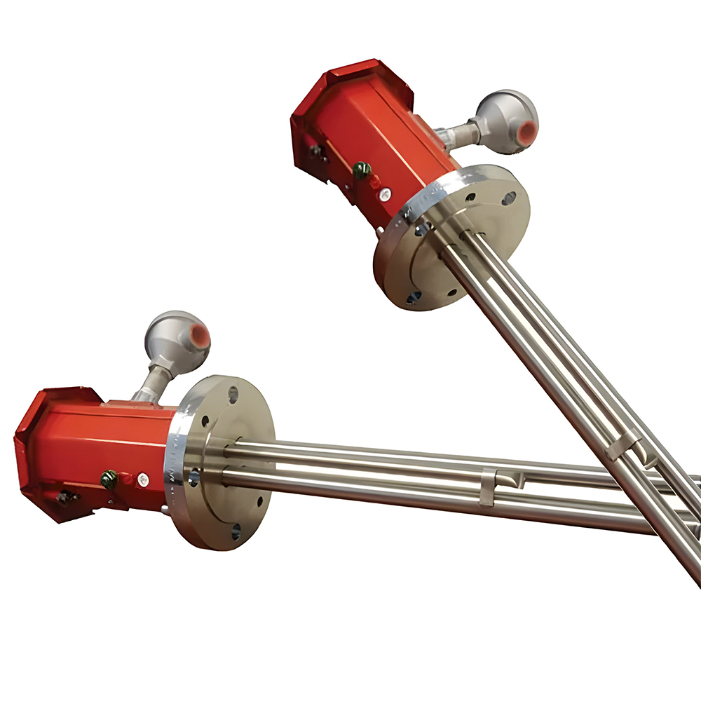
For industrial heat trace, the recommended schedule is an annual IR test at the panel level for all circuits, a full walk-down inspection of all runs every two to three years, and an immediate inspection following any maintenance activity — valve replacement, pipe repairs, insulation work — that involved the heat trace route. The full range of industrial heaters and controls designed for process temperature maintenance operates most reliably when paired with a documented preventive maintenance schedule that treats heat trace inspection as a routine system check rather than an emergency response.
 English
 русский
 Français
 Español
 عربى
عربى